Gyroscopic Instruments
Any spinning object exhibits gyroscopic properties. A wheel or rotor designed and mounted to utilize these properties is called a gyroscope.
Rigidity in Space
Rigidity in space refers to the principle that a gyroscope remains in a fixed position in the plane in which it is spinning. An example of rigidity in space is that of a bicycle wheel. As the bicycle wheels increase in speed, they become more stable in their plane of rotation. This is why a bicycle is unstable and maneuverable at low speeds but stable and less maneuverable at higher speeds. By mounting this wheel, or gyroscope, on a set of gimbal rings, it is able to rotate freely in any direction. Thus, if the gimbal rings are tilted, twisted, or otherwise moved, the gyro remains in the plane in which it was originally spinning.
Precession
Precession is the tilting or turning of a gyro in response to a deflective force. The reaction to this force does not occur at the point at which it was applied; rather, it occurs at a point that is 90° later in the direction of rotation. Precession can also create some minor errors in some instruments. Precession can cause a freely spinning gyro to become displaced from its intended plane of rotation through bearing friction. Certain instruments may require corrective realignment during flight, such as the heading indicator.
Sources of Power
A gyroscope must spin at incredible speeds to be effective. To achieve this they may be powered by an electric system or vacuum system.
- Electric: A small electric motor will drive the gyroscope to its operational speeds. The turn coordinator is typically electric powered on many general aviation aircraft.
- Vacuum: An engine driven pump may be used to drive certain gyros. The pump draws air at high speeds to spin a gyro similar to how a waterwheel is operated. Many general aviation aircraft have their attitude and heading indicator powered using a vacuum system.
Because of their importance, gyroscopic instruments are typically powered using different power sources. A combination of electrically driven and vacuum driven gyros are normally found on many general aviation aircraft. This is to ensure a loss of one system does not result in a complete loss of all gyroscopic instruments.
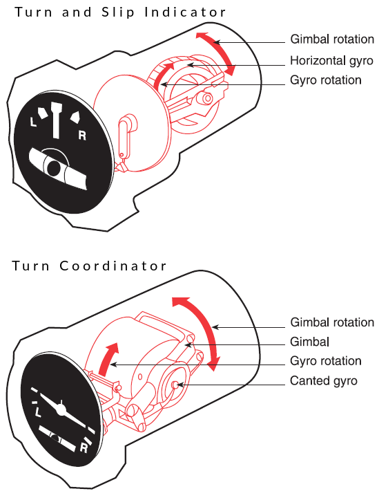
Turn and Slip Indicator
The gyro in the turn-and-slip indicator rotates in the vertical plane corresponding to the aircraft’s longitudinal axis. A single gimbal limits the planes in which the gyro can tilt, and a spring works to maintain a center position. Because of precession, a yawing force causes the gyro to tilt left or right, as viewed from the pilot seat. The turn-and-slip indicator uses a pointer, called the turn needle, to show the direction and rate of turn.
Turn Coordinator
The gimbal in the turn coordinator is canted; therefore, its gyro can sense both rate of roll and rate of turn.
Inclinometer
The inclinometer is used to indicate aircraft yaw. During coordinated, straight-and-level flight, the force of gravity causes the ball to rest in the lowest part of the tube centred between the reference lines. Coordinated flight is maintained by keeping the ball centred. If the ball is not centred, it can be centred by using the rudder.
The gyro in the attitude indicator is mounted in a horizontal plane and depends upon rigidity in space for its operation. The horizon bar represents the true horizon. This bar is fixed to the gyro and remains in a horizontal plane as the aircraft is pitched or banked about its lateral or longitudinal axis, indicating the attitude of the aircraft relative to the true horizon.
Limitations
The pitch and bank limits depend upon the make and model of the instrument. Limits in the banking plane are usually from 100° to 110°, and the pitch limits are usually from 60° to 70°. If either limit is exceeded, the instrument will tumble and will give incorrect indications until realigned.
The operation of the heading indicator depends upon the principle of rigidity in space. The rotor turns in a vertical plane and fixed to the rotor is a compass card. Since the rotor remains rigid in space, the points on the card hold the same position in space relative to the vertical plane of the gyro. The aircraft actually rotates around the rotating gyro, not the other way around. As the instrument case and the aircraft revolve around the vertical axis of the gyro, the card provides clear and accurate heading information.
Limitations
Because of precession caused by friction, the heading indicator creeps or drifts from its set position. Among other factors, the amount of drift depends largely upon the condition of the instrument. If the bearings are worn, dirty, or improperly lubricated, the drift may be excessive. Another error in the heading indicator is caused by the fact that the gyro is oriented in space, and the Earth rotates in space at a rate of 15° in 1 hour. Thus, discounting precession caused by friction, the heading indicator may indicate as much as 15° error per every hour of operation.