Non Precision Approaches [DELETE]
A non-precision approach is an instrument approach and landing which utilizes lateral guidance but does not utilize vertical guidance. Non-precision approaches make use of ground beacons and aircraft equipment such as VOR, NDB and LOC
For pilots of older aircraft, in which use of automated systems to assist in flying the approach is limited, a high degree of piloting skill is required to fly such approaches accurately and the frequent practice which many pilots need to achieve this can be difficult to come by if precision approaches are the normal method used.
A high proportion of Controlled Flight Into Terrain (CFIT) accidents have been shown to occur during non-precision approaches. This is in part a result of loss of situational awareness, e.g. resulting in descent before the initial approach fix; and in part a consequence of the lack of precise vertical guidance, which may involve levelling off at intermediate points between the initial approach fix and MDA/H (a step-down approach).
Controlled Flights Into Terrain (CFIT) continue to be a major threat to civil aviation safety in Canada. The step-down technique presumed by NPA procedure design may have been appropriate for early piston transport aircraft, but it is less suited to larger jet transport aircraft.
When using the step-down technique, the aircraft flies a series of vertical descents during the final approach segment as it descends and levels off at the minimum IFR altitudes published for each segment of the approach. The successive descents and level-offs result in significant changes in power settings and pitch attitudes and for some aircraft, may prevent the landing configuration from being established until landing is assured. Using the step-down technique, the aircraft may have to be flown at minimum IFR altitudes for each segment of the approach and consequently be exposed to reduced obstacle separation for extended periods of time. A premature descent or a missed level-off could render the aircraft vulnerable to a CFIT accident.
Many air operators require their flight crews to use a stabilized approach technique which is entirely different from that envisaged in the original NPA procedure design. The stabilized approach is calculated to achieve a constant rate of descent at an approximate 3° flight path angle with stable airspeed, power setting, and attitude, and also with the aircraft configured for landing. The safety benefits derived from the stabilized final approach have been recognized by many organizations including ICAO, the FAA and TCCA. Those air operators not already doing so are encouraged to incorporate stabilized approach procedures into their SOPs and training syllabi.
CAUTION: Caution should be exercised when descending below the MDA while following an FMS-generated vertical path. Unlike vertically guided approaches, which have their OCSs verified below the DA, OCSs on LNAV procedures below the MDA have NOT been assessed. As a result, obstacles may penetrate the computer-generated flight path. Pilots are reminded to visually scan for obstacles before descending below the MDA.
VASI and PAPI are calibrated for a defined geometric vertical path angle. In cold temperatures, a non-temperature compensated barometric FMS-generated vertical path may be lower than that of a calibrated VASI or PAPI. In high temperatures, a barometric FMS-generated vertical path will be higher than that of a calibrated VASI or PAPI. Pilots should be aware of this limitation and operate accordingly.
Constant Descent Angle
Constant Descent Angle (CDA) is a technique for flying the final approach segment of a non precision instrument approach procedure as a constant descent from an altitude at or above the final approach fix altitude. CDA information is provided as supporting information to the non precision approach procedure and it is the pilot’s responsibility to determine how he/she intends to use the information in flight. Although the constant descent angle accounts for all minimum segment altitudes between the procedure’s intermediate fix and the point of arriving at the MDA, it is still the pilot’s responsibility to ensure the aircraft is always operated at or above any minimum altitude. The constant descent angle is projected from:
- A point normally 50 feet above the aligned runway threshold for procedures meeting straight-in alignment,
- A point 50 feet above the aerodrome elevation abeam the earliest usable landing surface for circling only procedures which do not meet straight-in alignment, or
- The lowest MDA at the missed approach point for helicopter only procedures.
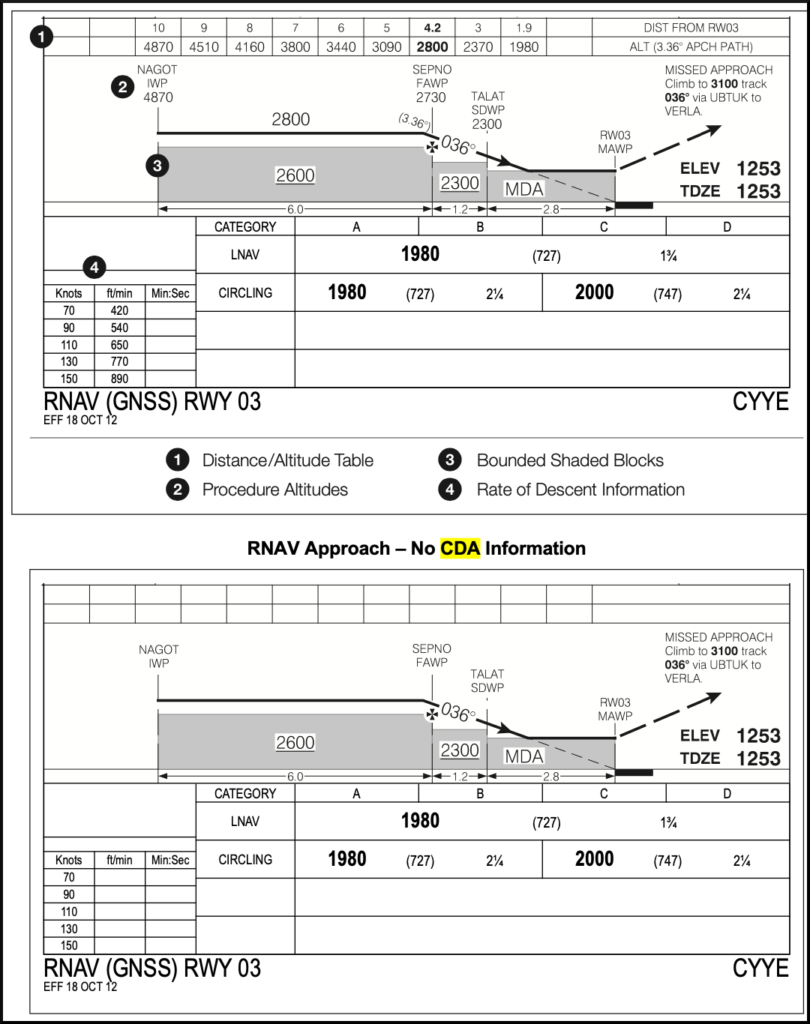
CDA depiction includes three elements:
- Distance / Altitude Table
- Procedure Altitudes, and
- Rate of Descent Information
CDA information is charted for every non-precision (non vertically guided) approach procedure that meets NAV CANADA’s criteria for the depiction of CDA information. This includes non-precision approach procedures that are combined with a precision approach procedure (i.e. NDB and LOC charted with an ILS). When a non-precision approach procedure does not meet NAV CANADA’s criteria for the depiction of CDA information, the CDA information is left uncharted.
REFERENCES
AIM RAC 2.16 Vertical Path Control on Non Precision Approaches
CAP GEN Instrument Approach Procedures